What a Managed Switch Actually Does — and Why It Matters More Than Ever
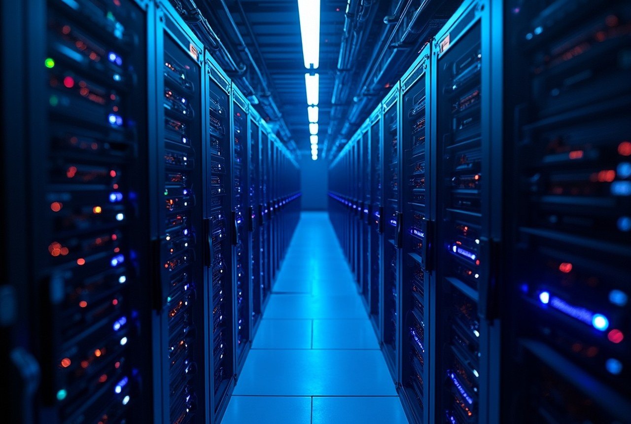
At its most fundamental level, every switch maintains a MAC address table and forwards Ethernet frames only to the correct destination port. A managed switch extends that baseline with remote configuration, VLANs, Quality of Service (QoS), redundancy protocols, and real-time telemetry — capabilities that unmanaged switches simply cannot offer. None of that was negotiable in traditional enterprise networks. In AI data centers, where thousands of GPUs exchange gradient updates continuously and a single dropped packet can stall an entire training cluster, the stakes are an order of magnitude higher.
Two architectural models dominate modern data-center networking, and understanding them is the prerequisite for every selection decision that follows.
The Classic Three-Tier Hierarchy
Enterprise and hyperscale data centers have long organized switching infrastructure into three distinct layers, each with its own performance profile, port-density requirement, and operational role.
Core switches sit at the top and carry the aggregated traffic of the entire facility. Their defining characteristics are switching capacity measured in terabits per second, sub-microsecond forwarding latency, and hardware-level redundancy: dual power supplies, hot-swappable line cards, and non-stop forwarding (NSF) capabilities that survive a control-plane restart without dropping a packet. Because core switches rarely terminate end-user devices, raw throughput matters more than port density. A well-designed core layer interconnects in a full-mesh or partial-mesh topology, eliminating single points of failure and enabling load balancing across multiple equal-cost paths via ECMP.
Distribution switches are where network intelligence concentrates. They aggregate uplinks from dozens of access switches, enforce inter-VLAN routing, apply access control lists (ACLs), and mark or remark QoS DSCP values before traffic reaches the core. Because they sit at the routing boundary, they require both Layer 2 and Layer 3 — what the industry calls multilayer switching. Two hardware details matter disproportionately at this tier: TCAM (Ternary Content Addressable Memory) depth determines how large an ACL and routing table the switch can hold in fast memory before falling back to slower software lookups; buffer memory determines how gracefully the switch absorbs traffic bursts from the access layer without dropping frames. Fast convergence through OSPF or BGP is a baseline expectation, not an option.
QoS classification at the distribution layer deserves emphasis. Pre-classifying queued traffic here ensures that latency-sensitive workloads — storage replication, real-time analytics, inter-GPU collective communications — are always served ahead of bulk transfers, regardless of instantaneous congestion. In AI training environments, where the slowest node in an all-reduce operation determines the pace of every node, this is not a minor operational nicety; it is architecturally load-bearing.
Access switches carry the highest port density in the stack and connect directly to compute and storage. In modern data centers this means 48-port 1/10/25 GbE downlinks with 40/100 GbE uplinks to the distribution layer. PoE+ and PoE++ capabilities at this tier power surveillance cameras, wireless access points, and edge IoT devices without separate power cabling. From a security standpoint the access layer is the first line of defense: 802.1X port-based authentication, Dynamic ARP Inspection, DHCP snooping, and MAC-based ACLs all operate here to prevent unauthorized devices from gaining network access.
| Layer | Job | Typical speeds | Watch for |
|---|---|---|---|
| Access / leaf | servers into the fabric | 10–100 GbE down, 400 up | oversubscription ratios |
| Distribution | policy, routing, aggregation | 100 GbE+ | QoS classification, convergence |
| Core / spine | non-blocking east-west mesh | 100/400 GbE | latency, buffering, radix |
Spine-and-Leaf: The AI-Era Default
The three-tier model works well for large enterprise environments with predominantly north-south traffic — client-to-server flows moving up and down the hierarchy. AI training clusters tell a different story. A thousand-GPU cluster running a distributed training job generates ferocious east-west traffic — GPU to GPU, all-reduce collective operations spanning the entire cluster simultaneously — and the asymmetry of a traditional three-tier topology introduces variable latency that can measurably slow convergence.
Spine-and-leaf solves this by replacing the pyramid with a flat two-tier mesh. Every leaf switch (functionally analogous to an access switch) connects to every spine switch (a collapsed core and distribution), and no two leaf switches connect directly to each other. The result is predictable, consistent hop count and latency for any server-to-server flow — critical for distributed GPU workloads, containerized applications, and software-defined networking overlays. Because every leaf has an equal-distance path to every other leaf through the spine layer, ECMP load balancing works with mathematical symmetry rather than approximation.
This topology pairs naturally with the AI cluster's interconnect layer. High-performance clusters typically run InfiniBand or RoCE (RDMA over Converged Ethernet) for GPU-to-GPU communication, but the broader data-center Ethernet fabric — carrying storage traffic, control-plane messages, and management — still follows a spine-leaf design. Keeping that Ethernet fabric non-blocking and low-latency is what allows the AI network fabric to operate without interference from background data movement.
Smaller data centers often collapse the core and distribution layers into a single high-performance switch pair — a "collapsed core" — reducing cost and operational complexity while preserving the essential logic of the hierarchy. At the opposite end of the scale, multi-fabric architectures virtualize many physical switches into a single logical management domain, simplifying operations while retaining physical redundancy.
Shallow-buffered switches optimized for financial trading latency are a poor fit for AI infrastructure.
Key Selection Criteria
Non-blocking capacity. The first number to verify is whether total port bandwidth exceeds the switching fabric's capacity. A switch that is nominally "non-blocking" only remains so if all ports are populated with optics running at their rated speeds. Do the arithmetic; do not trust marketing language.
Forwarding latency and switching mode. Store-and-forward switching buffers an entire frame before forwarding, adding latency proportional to frame size and port speed. Cut-through switching begins forwarding as soon as the destination address is read, delivering sub-microsecond port-to-port latency on capable silicon. For latency-sensitive workloads — AI collective operations, storage replication, real-time analytics — cut-through is strongly preferred where the network is clean enough to make it viable.
Buffer memory. Incast congestion — many senders simultaneously targeting one receiver — is endemic in both storage-heavy and AI training environments. Deep buffers absorb these bursts without tail-drop. Shallow-buffered switches optimized for financial trading latency are a poor fit for AI infrastructure.
TCAM and table sizes. Undersized MAC, ARP, and routing tables force traffic to software forwarding, collapsing throughput under scale. Verify the hardware limits against the expected number of endpoints, VLANs, and routing prefixes before procurement, not during a production incident.
Hardware redundancy. Dual hot-swap power supplies and fan modules are a minimum. For gateway redundancy at the distribution and spine layer, VRRP, HSRP, or MC-LAG (Multi-Chassis Link Aggregation) provides fast failover without topology changes. Five-nines availability targets (99.999%) are only achievable if every single-point-of-failure in the hardware BOM has been identified and eliminated.
Automation and programmability. REST APIs, NETCONF/YANG support, and compatibility with orchestration platforms such as Ansible and Terraform are now baseline expectations. AI data centers change topology frequently as GPU cluster configurations evolve; manually administered switch configs do not scale. Infrastructure-as-code for the network fabric is not aspirational — it is operationally necessary.
Optics flexibility. Vendor lock-in on optics can add meaningful cost at the scale of a large AI cluster with thousands of interconnected ports. Confirm whether the switch accepts third-party SFP+/QSFP/QSFP-DD transceivers before committing to a platform, and model the total cost of ownership accordingly.
Power efficiency. AI data-center racks that once drew 5–10 kW now routinely pull 40–130 kW, and the facility PUE metric captures total power consumption relative to IT load. Switching infrastructure is a smaller contributor than GPU servers, but at hyperscale quantities it is not negligible. Evaluate watts-per-port alongside headline throughput.
Putting It Together
A well-architected managed switching fabric is the connective tissue that turns a collection of GPU servers into a functional training cluster. The three-tier model provides a proven baseline for medium-to-large deployments with mixed traffic profiles. Spine-and-leaf better serves cloud-native, AI-centric environments where east-west traffic dominates and predictable latency is non-negotiable. The selection criteria remain consistent across both architectures: non-blocking capacity, deterministic latency, deep buffers, adequate TCAM, hardware redundancy, and the programmability to adapt as workloads change.
Evaluating switches against those criteria — rather than headline port counts or unit price — is what separates infrastructure that scales gracefully through successive GPU generations from infrastructure that becomes the bottleneck the moment the next growth cycle begins.